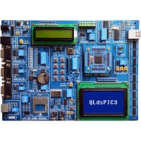
The QLdsPIC3 development board is an experimental development board designed integrating its main characteristic function module based on variety of 16-bit microcontroller DEMO boards home and aboard, the main circuit of which origins from the standard DEMO board and reference application circuit of MICROCHIP Co. The design of board resource is completely open which can be flexibly extended, is a good assistant for mass of engineers to deal with the 16-bit MICROCHIP microcontroller software and hardware design.
The QLdsPIC3 development board supports PIC24FJ96GA008 and other chips compatible with pin, and the chip module can be changed.
The QLdsPIC3 development board supports dsPIC30F6014A and other chips compatible with pin, and the chip module can be changed.
The QLdsPIC3 development board supports dsPIC33FJ128GP708 and other chips compatible with pin, and the chip module can be changed.
Preprogrammed dsPIC30F6014A Plug-in Module, VDD =5V, Crystal for 10Mhz, On each corner of the card there is one electrolytic capacitor for stable power supply.
Open modular design: All modules can be on/off controlled by DIP switch. Each module is designed to connect to I/O port of Microcontroller. Connection of module with any port of Microcontroller is conveniently achieved through dupont thread. Connection to preset port is available by using DIP switch without dupont thread. All I/O ports are open externally with output socket. Expansion is easily accomplished.
On-board simulation debugging and Programmer interface: direct connection to ICD2/ICD3/MCD2/PICKIT2
The master controller is in independent design and it’s easy to change.
1) Power supply module, Jump select VDD for 5V or 3.3V
2) Master controller chip module
3) ICSP Connect port,it can connect icd2/icd3/mcd2/pickit2 for program or debug,
4) Master controller chip ICSP I/O Pin select.
5) Reset key-press
6) LED module
7) Key-press module
8) A/D converter input module
9) DS18B20 digital thermometer module
10) Real time clock module by PCF8583
11) 16*2-character LCD
12) 16*2 LCD backlight potentiometer
13) 128*64- Graphic LCD
14) 128*64 LCD backlight potentiometert
15) SD/MMC card Read/Write Module
16) PS2 module
17) CAN bus module by mcp2551
18) RS232 module B
19) RS232 module A
20) RS-485 and RS-422 communication module by MAX489E
21) Ethernet module by ENC28J60
23) All pins are taken out on IDC10 connectors to make them available for further connections.
Sample with C30 Program sources code as below (using dsPIC30F6014):
8x LED
RS232 Communication
RS485 Communication
Can Communication
PS2
Real time clock
Si3000 Voiceband Codec
DS1820
MMCSD card Read/Write
128x64 GLCD
1602 LCD
Key-press
A/D converter
The packing includes
QLdsPIC3 DEVELOPMENT Board (Include one dsPIC30F6014A chip module,one 16*2 LCD,one 128*64 LCD)
RJ45 LAN Cable
RJ12 to RJ12 ICSP cable
Dupont thread expansion connection 20x wire
DC wall adapter(input: AC110-240V 50/60Hz, output: DC9V 1000mA)
CD-ROM (English version PDF User manual ,PCB Board Layout PDF,Schematic PDF , Sample code (C30) , MPLAB IDE, Chip's Datasheet)
Online Order Now! Global Shipping in 2 days!

We accept online order and ship globally, our online order system will tell shipping fee according to your address, and automaticly generate PI Invoice to you.
Please send email to us if you have any question for this product, or want product document in more detail, or question for order or payment or shipping. Contact information is at the bottom of the page.
Sample price is announced hereby above. Ask for quotation when order quantity > 3pcs.
Parts of product, like core module, SBC, stamp, daughter card, single board(without LCD), motherboard, baseboard, LCD, sell seperately, email us for quatation.
find gps,gprs,wifi,camera etc in modules and bluetooth,485,can etc in accessories, or enclosures, jlink v8, ulink, openjtag etc tools.
We are now offer Capacitive Touch Panel for all of our ARM platforms.
Product Warranty and Technical Support.
Our delivery has mass producing quality assurance. We warrants our products against manufacturing defects for a period of one year from date of shipment to the original purchaser, and offers software updates lifetime to registered customers free of charge. We have an experts team to provide technical support.
We have been running 8 years, this is our license from Chinese government website:
http://www.sgs.gov.cn/LicenceView/Id=20120530152953117
We have served 1000+ customers from 100+ countries all over the world, Please find a list of part of our customers here:
http://www.quickembed.com/Tools/Shop/Customer/Index.html
We can provide contact if you want a reference.
We are looking for sell/retail/ditribute/channel partners in all over the world.
You are encouraged to share your information in the forum, share your business information, share your success, it will get you more business and success!
If you need some partner, technical, hardware, software, marketing, channel, sales, just post your message on the forum, because someone in the world may be finding you!
Our world and technology is changing and growing so fast that no one no single company can do all work, clever people can get information from the web and try to make it but will take a lot time to learn, we need cooperation!
Promote your product in the forum, or just an idea, don't be afraid other will copy, there are similar products and ideas all over the world, the only difference is who will make it real in a right time in success!
If you want more formal, list your product in our web catalog, to promote it to all over world, we are open, please send email to us.
We can build a prototype sample very fast, for you, to demonstrate, to your customer.
A demo is much more powerful than a thousand words!
It will save you a lot of valuable time!
Make a concrete step from good idea to real success!
We help you succeed, providing ARM Embedded Quick Demo.
ODM/OEM Service
Layout, for special defined interface and resize the board for your requirements.
Product prototyping, sourcing accessories for your product requirements.
Recommend GPS module, GSM/GPRS module with communication software.
Software Developing.
Sourcing solution and turn key to you.
You might have interest to know what products this board makes, please send us an email to know more product design cases. Embedded pc computer system has broad usge, some examples:
QButton, world first post-it bluetooth sensor, open data, customize for your usage.
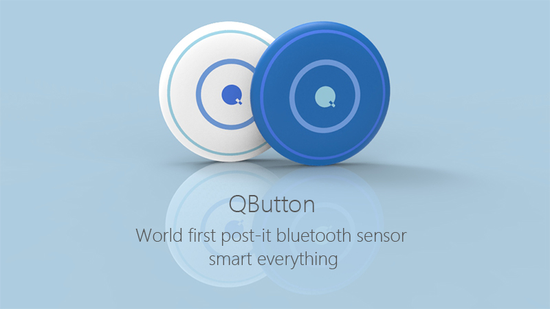
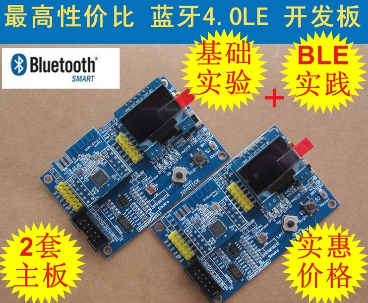
Popular bluetooth v4.0 ble sensor tag, smart devices, wearable electronic computer.
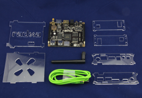
Palm size desktop computer.
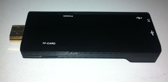
U-disk size computer
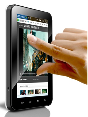
Android 4.0 5inch 7inch capacitive touch pad
9D position pose system digital compass
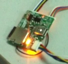
GPS, Compass and accelerator in one tiny module.
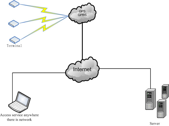
GPS GPRS LBS solution.
Navigate Locate Track Solution, Location Based Service
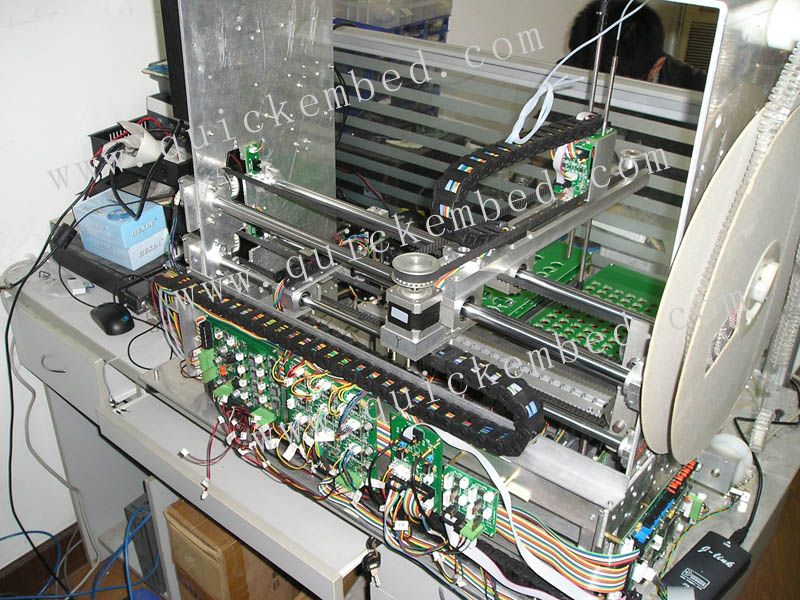
Robot Motor Medical Testing System
One motor control board controlling 9 motors at the same time
Robot arm move and grab.
12" to 15" size multimedia or HMI solution, fixed on wall or desk or large vehicle:
Backside:
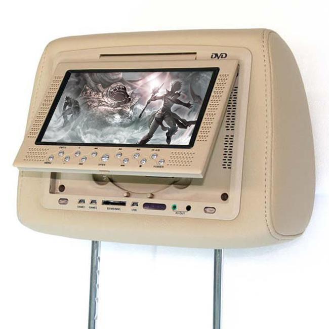
10" solution, fixed in car:
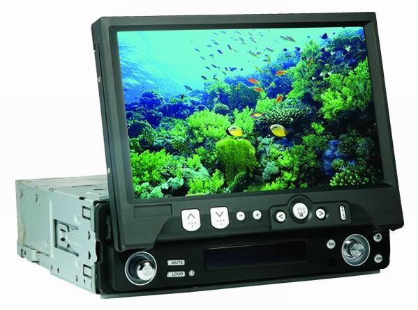
7" solution, fixed in car:
more 7inch cases here:
http://www.quickembed.com/Tools/Shop/Solution/201001/67.html
Using SBC is as easy as 1,2,3; simply prototype and test your development using a suitable SBC, then design your custom connector board and finally build your product.
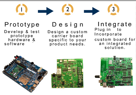
The advantage of SBC is that when you define a new product, you have only small change on baseboard/motherboard, no change on SBC/daughter board, it saves great effort, and save much expense as the SBC is big lots produced while baseboard can be produced in small lots, also this helps improving the quality of your products.
Read more about arm board customize design odm service.
Read more about arm linux driver and application software develope.
Our mission is to provide quick start and easy use embedded platforms for maximize customers productivity. If you find any platform more competitive than ours, please do let us know. We can improve our product for you.
Those who want to list your product here in this web and sell to worldwide customers, please contact us.
-- Stay Hungry. Stay Foolish. Memory of Steve Jobs.
-- Dream bigger, Love Deeper, Live Longer! :-)
|